

TL;DR: Let’s create UML exercise diagrams utilizing the React Diagram Library. This weblog covers every thing from establishing the diagram floor to including shapes and connectors and customizing the looks. You’ll learn to characterize actions, choices, and the circulate of management in your diagrams. The library affords a wealthy set of options for creating interactive and visually interesting UML exercise diagrams.
Unified Modeling Language (UML) exercise diagrams are a superb instrument for visually representing the circulate of management or knowledge in a system. From modeling advanced enterprise processes to defining workflows, UML exercise diagrams make it straightforward to research and design programs successfully.
On this article, we’ll discover the right way to create an interactive UML exercise diagram utilizing the Syncfusion React Diagram Library.
Discuss with the next picture.

What’s a UML exercise diagram?
A UML exercise diagram gives a graphical illustration of a system’s actions, exhibiting the sequence during which actions are executed. The important thing parts embody:
- Exercise nodes: Symbolize actions or duties.
- Management flows: Arrows indicating the circulate from one exercise to a different.
- Resolution nodes: Diamond-shaped nodes used for branching paths based mostly on circumstances.
- Begin and finish nodes: Particular symbols representing the start and finish of a course of.
UML exercise diagram notations and their meanings
|
Form |
Picture |
Description |
|
Motion |
 |
Represents a selected job or motion within the workflow. |
|
Resolution |
 |
Represents a choice level within the circulate the place a number of paths will be taken based mostly on circumstances. |
|
MergeNode |
 |
Combines a number of incoming flows right into a single outgoing circulate. |
|
InitialNode |
 |
Represents the place to begin of the exercise. |
|
FinalNode |
 |
Signifies the tip of an exercise circulate. |
|
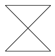
ForkNode |
Splits a single incoming circulate into a number of concurrent outgoing flows. |
|
|
JoinNode |
Synchronizes a number of concurrent incoming flows right into a single outgoing circulate. | |
|
TimeEvent |
 |
Represents a delay or timed set off within the exercise. |
|
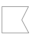
AcceptingEvent |
 |
Represents an occasion that waits for a selected sign or situation. |
|
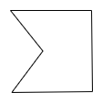
SendSignal |
 |
Represents the motion of sending a sign. |
|
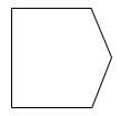
ReceiveSignal |
 |
Represents the motion of receiving a sign. |
|
StructuredNode |
 |
Represents a bunch of actions executed as a single unit or block. |
|
Observe |
 |
Represents a remark or extra info related to the diagram. |
|
Object/ Management |
 |
A connector object representing a relationship with UML exercise nodes |
|
Exception |
 |
A connector object representing a relationship Exception with UML exercise nodes |
Stipulations
- Set up Node.js model – 14.15.1, 14.17.3, 18.20.0
Making a diagram floor
Let’s create a diagram floor by following these steps.
Step #1: Create a folder and title it as UML Exercise Diagram.
Step #2: Create a brand new React app utilizing the command npx create-react-app my-diagram-app. Exchange my-diagram-app along with your desired app title. As an example, should you want to create an app named uml-activity, you should utilize the next command:
npx create-react-app uml-activity
Step #3: Navigate to your app listing. Change your working listing to the newly created app utilizing the next command:
cd uml-activity
Step #4: Run the next command to start out the event server and look at your app in motion.
npm begin
This can open your app in your default net browser at http://localhost:3000/.
Step #5: Then, open the bundle.json file and add the next crucial bundle dependencies.
"dependencies": {
    "react": "18.1.0",
    "react-dom": "18.1.0",
    "@syncfusion/ej2-base": "*",
    "@syncfusion/ej2-react-base": "*",
    "@syncfusion/ej2-diagrams": "*",
    "@syncfusion/ej2-react-diagrams": "*"
  },
Step #6: Use the next command to put in all dependent packages.
npm set up
Step #7: Now, add the dependent scripts and magnificence CDN reference to the index.html file.
<head>
  <meta charset="utf-8">
  <title>React UML Exercise Diagram</title>
  <base href="https://www.syncfusion.com/">
  <meta title="viewport" content material="width=device-width, initial-scale=1">
  <hyperlink rel="icon" sort="picture/x-icon" href="favicon.ico">
  <script src="https://cdn.syncfusion.com/ej2/syncfusion-helper.js" sort ="textual content/javascript"></script>
  <hyperlink href="https://cdn.syncfusion.com/ej2/26.1.35/materials.css" rel="stylesheet"/>
</head>
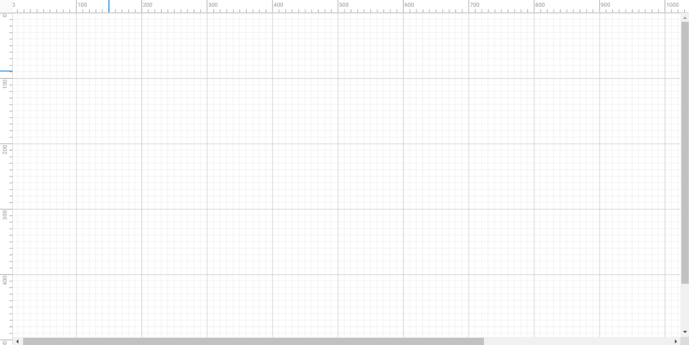
Step #8: So as to add the React Diagram element to your app, import the DiagramComponent from the ej2-react-diagrams bundle. Make sure that you specify the mandatory arguments, such because the width, peak, and assortment of nodes and connectors, inside the app.element.html file.
Discuss with the next code instance.
<div id="diagram-space" className="sb-mobile-diagram">
 <DiagramComponent id="diagram" ref={diagram => (diagramInstance = diagram)} width={"100%"} peak={"700px"}>
 </DiagramComponent>
</div>
The next picture illustrates the preliminary diagramming web page.
Observe: For extra particulars, consult with the getting began with React Diagram Library documentation.
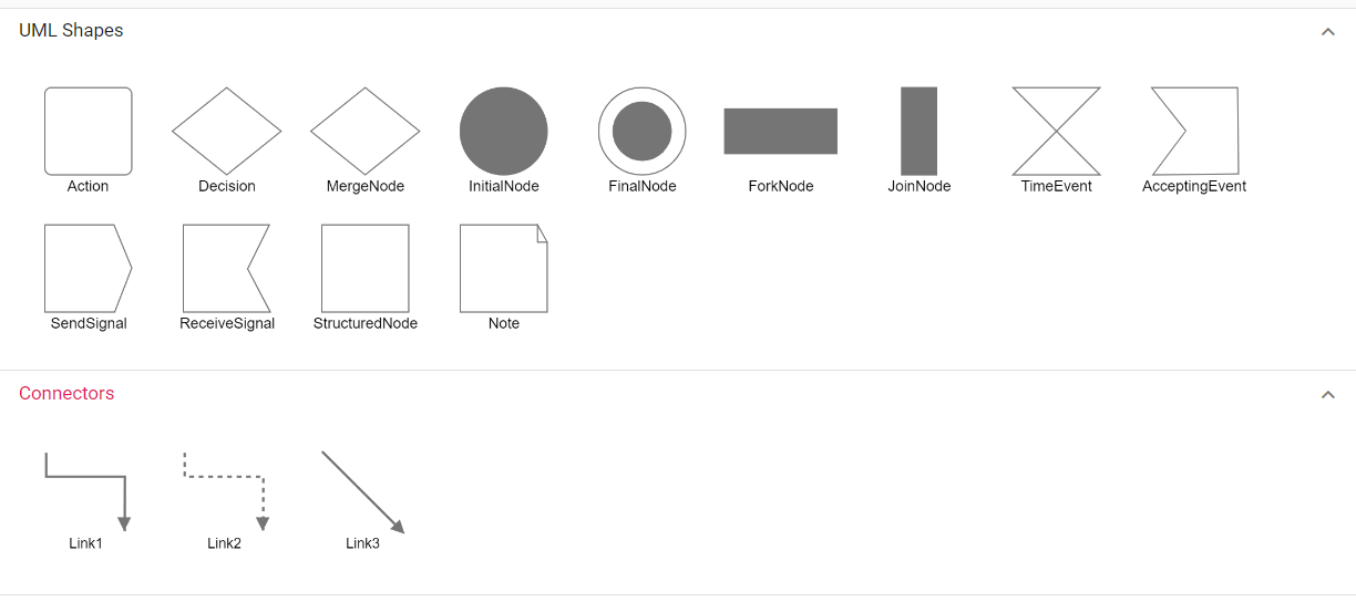
Including UML exercise shapes within the image palette
The React Diagram Library gives a gallery of reusable nodes and connectors known as SymbolPalettes. It shows a group of palettes, every exhibiting a set of nodes and connectors. We will drag and drop them onto the diagram canvas any variety of occasions.
The UML built-in shapes will be simply rendered in an emblem palette. The symbols property of palettes is used to outline UML symbols utilizing the mandatory parameters. This characteristic means that you can add a group of pre-defined UML symbols to the palette, making your UML diagramming app extra versatile.
Comply with these steps to create a diagram image palette with UML exercise shapes.
Step 1: Put together the container
Start by creating an HTML <div> factor to behave because the container for the image palette.
<div id="paletteSpace" >
  <SymbolPaletteComponent id="symbolpalette" width={"100%"} peak={"500px"}>
  </SymbolPaletteComponent>
</div>
Step 2: Initialize the image palette
Subsequent, initialize the React Diagram image palette by specifying the mandatory parameters, resembling width and peak, and the gathering of symbols to be included within the palette.
Discuss with the next code instance.
<SymbolPaletteComponent
  id="symbolpalette"
  expandMode="A number of"
  palettes={[
    {
      id: "umlActivity",
      expanded: true,
      symbols: umlActivityShapes,
      title: "UML Shapes",
    },
    {
      id: "connectors",
      expanded: true,
      symbols: connectorSymbols,
      title: "Connectors",
    },
  ]}
  width="100%"
  peak="505px"
  symbolHeight={100}
  symbolWidth={100}
/>
Step 3: Customise the image assortment
Now, outline a group of symbols to be included within the palette, which will be custom-made in accordance with your wants.
Discuss with the next code instance so as to add the UML exercise shapes and connectors.
let umlActivityShapes = [
  { id: 'Action', shape: { type: 'UmlActivity', shape: 'Action' } },
  { id: 'Decision', shape: { type: 'UmlActivity', shape: 'Decision' } },
  { id: 'MergeNode', shape: { type: 'UmlActivity', shape: 'MergeNode' } },
  { id: 'InitialNode', shape: { type: 'UmlActivity', shape: 'InitialNode' } },
  { id: 'FinalNode', shape: { type: 'UmlActivity', shape: 'FinalNode' } },
  { id: 'ForkNode', shape: { type: 'UmlActivity', shape: 'ForkNode' } },
  { id: 'JoinNode', shape: { type: 'UmlActivity', shape: 'JoinNode' } },
  { id: 'TimeEvent', shape: { type: 'UmlActivity', shape: 'TimeEvent' } },
  { id: 'AcceptingEvent', shape: { type: 'UmlActivity', shape: 'AcceptingEvent' } },
  { id: 'SendSignal', shape: { type: 'UmlActivity', shape: 'SendSignal' } },
  { id: 'ReceiveSignal', shape: { type: 'UmlActivity', shape: 'ReceiveSignal' } },
  { id: 'StructuredNode', shape: { type: 'UmlActivity', shape: 'StructuredNode' } },
  { id: 'Note', shape: { type: 'UmlActivity', shape: 'Note' } },
];

let connectorSymbols = [
  {
    id: 'Link1',
    type: 'Orthogonal',
    sourcePoint: { x: 0, y: 0 },
    targetPoint: { x: 40, y: 40 },
    targetDecorator: {
      shape: 'Arrow',
      style: { strokeColor: '#757575', fill: '#757575' },
    },
    style: { strokeWidth: 2, strokeColor: '#757575' },
  },
  {
    id: 'Link2',
    type: 'Orthogonal',
    sourcePoint: { x: 0, y: 0 },
    targetPoint: { x: 40, y: 40 },
    targetDecorator: {
      shape: 'Arrow',
      style: { strokeColor: '#757575', fill: '#757575' },
    },
    style: { strokeWidth: 2, strokeDashArray: '4 4', strokeColor: '#757575' },
  },
  {
    id: 'Link3',
    type: 'Straight',
    sourcePoint: { x: 0, y: 0 },
    targetPoint: { x: 40, y: 40 },
    targetDecorator: {
      shape: 'Arrow',
      style: { strokeColor: '#757575', fill: '#757575' },
    },
    style: { strokeWidth: 2, strokeColor: '#757575' },
  },
];
Discuss with the next picture.
Rendering the UML exercise diagram utilizing the React Diagram Library
UML exercise nodes
The React Diagram Library helps various kinds of UML exercise shapes, as outlined within the above desk.
Let’s create a UML exercise diagram to characterize a buyer name log assist state of affairs.
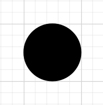
Step 1: To create a UML Exercise, outline the sort as UmlActivity and set the listing of built-in shapes within the form property as InitialNode.
let node = [
     {
        id: "Start",
        height: 40,
        width: 40,
        offsetX: 300,
        offsetY: 40,
        shape: { type: "UmlActivity", shape: "InitialNode" }
      },
];
Discuss with the next picture.
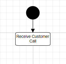
Step 2: Log the client name as Obtained Buyer Name. You’ll be able to outline this by setting the form property as Motion as demonstrated within the following code instance.
[
  {
    id: "Start",
    height: 40,
    width: 40,
    offsetX: 300,
    offsetY: 40,
    shape: { type: "UmlActivity", shape: "InitialNode" },
  },
  {
    id: "ReceiveCall",
    height: 40,
    width: 105,
    offsetX: 300,
    offsetY: 120,
    shape: { type: "UmlActivity", shape: "Action" },
    annotations: [{ content: "Receive Customer Call" }],
  },
];
UML exercise connector
To ascertain a UML Exercise connector, specify the sort of connector form as UmlActivity and outline the circulate as both Exception, Management, or Object. This configuration delineates the character of the connection, permitting for a exact illustration of the interplay inside the exercise diagram.
The next code illustrates the right way to create a UmlActivity connector.
var diagram;

var connector = {
  id: 'connector',
  sort: 'Straight',
  // Outline connector begin and finish factors
  sourcePoint: { x: 100, y: 100 },
  targetPoint: { x: 200, y: 200 },
  form: { sort: 'UmlActivity', circulate: 'Object' },
};

diagram = new ej.diagrams.Diagram(
  {
    width: '100%',
    peak: '600px',
    connectors: [connector],
  },
  '#factor'
);
UML exercise diagram circulate
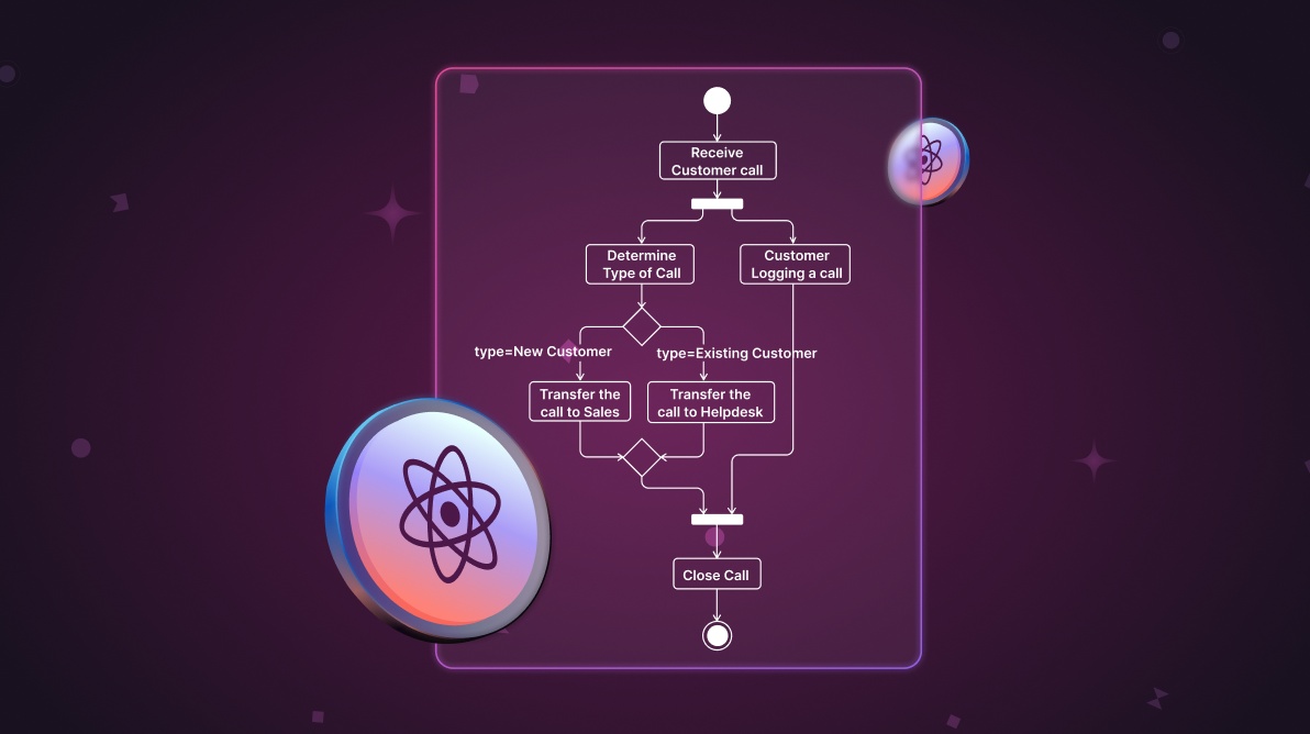
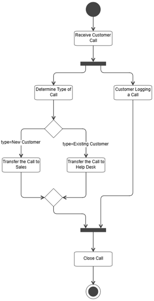
The next UML exercise diagram circulate delineates a structured course of for managing buyer calls. It covers key actions resembling receiving calls, figuring out buyer sort, logging particulars, and decision-making. Using nodes for parallel duties, synchronization, and circulate merging to make sure environment friendly and seamless workflow execution by means of the usage of Diagram nodes and connectors.
Nodes
- Begin (InitialNode): Marks the entry level of the method.
- ReceiveCall (Motion): Represents receiving a buyer’s name.
- ForkNode: Splits the method into two parallel flows.
- Decide (Motion): Determines the kind of name.
- Log (Motion): Logs the client’s name.
- Resolution: Resolve the decision’s subsequent step based mostly on the client sort:
- New buyer: Transfers the decision to gross sales.
- Present buyer: Transfers the decision to the assistance desk.
- MergeNode: Merges the paths after dealing with buyer calls.
- JoinNode: Synchronizes the logged name and merged paths.
- CloseCall (Motion): Closes the decision.
- FinalNode: Marks the method finish.
Movement
- The method begins on the Begin node.
- The decision is obtained and break up on the ForkNode.
- In parallel:
- Decide the decision sort that results in a Resolution:
- New clients are transferred to Gross sales.
- Present clients are transferred to the Assist Desk.
- The decision is Logged.
- Decide the decision sort that results in a Resolution:
- After name dealing with, paths converge on the MergeNode after which be part of on the JoinNode with the logged knowledge.
- Lastly, the decision is Closed, and the method ends on the FinalNode.
The diagram successfully fashions parallel processing, decision-making, and merging flows in a buyer name administration state of affairs.
Including shapes at runtime
Drag and drop the specified symbols from the palette to dynamically create a UML exercise flowchart. Double-click on nodes and connectors to edit their content material and embody circulate knowledge within the diagram objects.
Discuss with the next GIF picture.
Loading and saving a diagram
The React Diagram Library gives a helpful characteristic that means that you can save your work and resume it later by loading the saved diagram again onto the diagram canvas.
Saving your diagram
To save lots of your present diagram, select the Save Diagram choice from the toolbar. This can save your diagram as a file in your native drive.
Loading an current diagram
To load an current diagram file, choose the Open Diagram choice within the toolbar. This can open the file dialog field the place you may browse and choose the saved diagram file you want to load.
This characteristic affords important flexibility and comfort, enabling you to simply resume the place you left off on a diagram or make modifications to a beforehand saved diagram. It’s a necessary characteristic for any diagramming app that permits customers to create and handle advanced diagrams.
Discuss with the next GIF picture.
Export a diagram
You’ll be able to export the created UML exercise diagram as a picture file in numerous codecs, resembling JPEG, PNG, and SVG. By exporting the diagram as a picture file, you may simply share it by way of e mail or different digital means or embed it in a doc or presentation.
To do that, click on the Export button within the toolbar and choose the specified picture file format to save lots of the UML exercise diagram. You may select to export solely the content material space of the diagram, excluding clean areas, or export all the diagram (together with clean areas) based mostly on the width and peak specified within the web page settings.
Discuss with the next picture.
Print a diagram
To print a diagram, click on the Print button within the toolbar. This motion will open the Print dialog field, the place you may choose your printer and customise varied print settings, resembling orientation, paper measurement, and web page margins. After making the mandatory changes, click on the Print button to print the UML exercise diagram.
Discuss with the next picture.
Pan and zoom
The React Diagram Library helps the next panning and zooming choices.
- Pan utilizing the scrollbars: To pan straightforwardly, use the scrollbars situated on the fitting facet and backside of the diagram. This lets you scroll within the desired course.
- Pan utilizing the mouse wheel: To pan utilizing the mouse wheel, rotate it ahead or backward to scroll up or down. For horizontal panning, maintain the Shift key whereas rotating the scroll wheel ahead or backward.
- Pan utilizing the pan instrument: Another choice is to pick out the Pan instrument from the toolbar. Then, maintain down the left mouse button and drag to maneuver the diagram in any course. Discuss with the next picture for extra info.
Panning a UML exercise diagram - Zoom utilizing keyboard shortcuts: Probably the most environment friendly option to zoom out and in of the diagram is by utilizing the Ctrl + mouse wheel shortcut.
- Zoom utilizing the toolbar choice: Alternatively, use the zoom dropdown within the toolbar to regulate the zoom ranges. Discuss with the next picture.
Reference
For extra particulars, consult with the creating UML exercise diagram utilizing the React Diagram Library Stackblitz demo.

Attempt It Free
Conclusion
Thanks for studying! This weblog publish demonstrates the right way to simply create a UML exercise diagram utilizing the Syncfusion React Diagram Library. Equally, you may create diagram apps resembling a corporation chart creator, a circulate chart creator, or a community diagram creator.
For those who’re already a Syncfusion person, you may obtain the product setup from our web site. In any other case, you may obtain a free 30-day trial.
Please tell us within the feedback part beneath when you have any questions. You may as well contact us by means of our assist discussion board, assist portal, or suggestions portal. We’re at all times glad to help you!