

On this weblog, Akshra will showcase the 1st and threerd place winners of the MathWorks Simulation Problem award for the SAE AutoDrive II Yr 1 competitors, and the way they used MATLAB and Simulink to mannequin their methods.
Introduction
Simulation in an vital software to have in your system growth toolkit. For automated driving methods, testing fusion, planning, and controls algorithms require the usage of a mess of check situations. These check situations can vary from a straight highway check to an edge case check for an Automated Emergency Braking algorithm. Simulation supplies a secure and strong setting to design, check, and validate your methods.
This weblog will briefly cowl the first and third place winners of the 2022 Problem (College of Toronto and The Ohio State College), their system design, and the way they used MathWorks instruments to assist obtain general competitors goals. The groups had been judged primarily based on how they used the instruments to carry out the next duties in simulation:
- Simulate waypoint following
- Simulate visitors alerts and indicators interactions
- Simulate collision avoidance
- Check generated code with simulation
College of Toronto (aUTornoto)
System Necessities and Metrics
The group started with defining their high-level purposeful system necessities and baseline situations to check them.
- System shall generate and observe waypoints that result in a given aim place
- System shall obey visitors signal and light-weight guidelines
- System shall keep away from obstacles on the highway
These necessities had been then damaged into planning and controls necessities. A few of them embrace:
- Planner shall mark as occupied all cells containing obstacles and keep away from them
- Planner shall assign zero pace at any cease signal and cease mild
- Controller shall generate a pace profile and command automobile torque to realize it
As soon as the system necessities and checks had been written, the group needed to outline metrics that may consider efficiency throughout situations. A few of these metrics are summarized in Desk 1. These metrics had been mapped to the three duties of waypoint following, lights and indicators interactions, and impediment avoidance. Acceleration and jerk metrics had been additionally thought-about to be able to quantify passenger consolation efficiency.
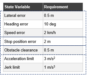
Desk 1: System Metrics (©aUToronto)
Software program Structure
The group’s software program structure had two key options:
- Modularity – Fashions and features had been developed individually and linked utilizing Simulink linked subsystems/reference subsystems. Once you add a masked library block or a Subsystem block from a library to a Simulink mannequin, a referenced occasion of the library block is created. Such referenced occasion of a library block accommodates hyperlink or path to the mother or father library block. The hyperlink or path permits the linked block to replace when the library block is up to date.
- Mannequin-Primarily based Design Workflow – This workflow begins with a V diagram (Determine 1) containing necessities, design, implementation, then integration and testing. System-level and subsystem-level design, implementation, and unit checks make a profitable implementation of the model-based design workflow.
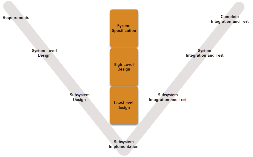
Determine 1: V Diagram for Mannequin-Primarily based Design Workflow
The group’s system was break up into simulator, planning, and controls modules. Determine 2 reveals the linked Simulink blocks for the three modules.
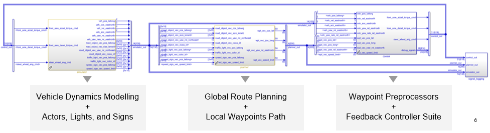
Determine 2: Excessive-Degree Code Structure in Simulink (©aUToronto)
The simulator module fashions automobile dynamics and state of affairs technology, and outputs automobile states and highway actors. The planning module computes optimum international route and native waypoints, and outputs reference waypoints. The Controls module preprocesses these waypoints and performs suggestions management, and outputs actuator instructions
Planning Module
The group evaluated 5 completely different planning algorithms throughout weighted standards of answer optimality, dynamic feasibility, processing time, and collision avoidance. A Pugh matrix was constructed (determine 3) to be able to choose a worldwide route planner and an area waypoint planner. The A* algorithm scored the best for path optimality, therefore was chosen as the worldwide planner. The Hybrid A* algorithm scored high factors for path smoothness, therefore was chosen because the native planner.

Determine 3: Pugh Matrix for Planner (©aUToronto)
Controls Module
The group evaluated 6 algorithms throughout weighted standards of disturbance rejection, monitoring error, constraint enforcement, and computation time. 2 Pugh matrices had been created to be able to choose lateral and longitudinal controllers. The Mannequin Predictive Controller was chosen for each. First, body transforms to native inertial and automobile physique fastened frames had been carried out, then waypoint resampling was performed to interpolate the planning path. Velocity scheduling was performed to create a easy velocity profile for the deliberate path. The MPC’s output is fed by way of a PI controller to reject mannequin mismatch errors. Lastly feedforward actuator mapping is carried out. These processes are proven in Determine 4.
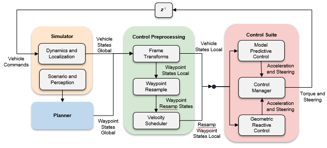
Determine 4: Management Design (©aUToronto)
Simulation Outcomes
The group examined their system in 3 situations – waypoint following, impediment avoidance, and alerts and indicators interactions. All simulation outcomes had been obtained in Simulink with the assistance of ROS2 bridges. Efficiency plots had been generated for all (Determine 5) and simulation insights had been obtained.
Waypoint following – Pace and lateral place errors met the requirement. Nevertheless, state error efficiency needed to be traded off to be able to meet group drive high quality metrics.
Impediment avoidance – The minimal distance to impediment exceeded necessities. Nevertheless, horizon size needed to be traded off to be able to cut back computation price.
Alerts and indicators – The automobile was capable of exceed the utmost stopping distance requirement. Nevertheless, planning and management horizon needed to be elevated to satisfy braking distance necessities.
Determine 5: Simulation Efficiency Plots (©aUToronto)
Challenges and Options
The group confronted a number of challenges alongside the way in which. Considered one of these challenges was planner-control synchronization points. The principle causes for this had been ROS2 asynchronous communication points, algorithm latency, and distance between waypoints. The group solved this by constructing a waypoint resampler that would interpolate/lengthen paths as wanted and assure management feasibility. One other problem was the planner’s path feasibility whereas decreasing computation pace for situations involving corners. The group expanded their error dealing with and time-out functionalities to deal with this concern.
The Ohio State College (Buckeye AutoDrive)
System Structure
The group developed Simulink fashions that carried out controls, path planning, notion and decision-making duties. The trail planner took velocity suggestions as enter from the controllers and output path data. The controllers took data from the decision-making logic and notion blocks, and output torque, brake, and steering instructions to the automobile dynamics block, which then despatched ego automobile data to the state of affairs floor reality block.
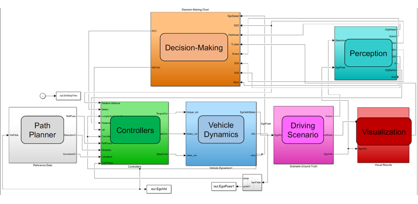
Determine 6: General System (©Buckeye AutoDrive)
Waypoint Following Utilizing Controllers

Determine 7: Controllers for Waypoint Following (©Buckeye AutoDrive)
The longitudinal Stanley controller takes in reference velocity and present ego automobile velocity, and outputs longitudinal acceleration and deceleration instructions. These outputs are then transformed to torque and brake instructions to be despatched to the Automobile Dynamics block.
The lateral Stanley and Pure pursuit controllers output steering instructions that are fed to the Automobile Dynamics block as steering wheel angle. Parameters reminiscent of yaw fee suggestions achieve, steering angle suggestions achieve, place achieve, lookahead distance, and automobile set pace had been tuned and set by the group. Determine 8 compares lateral heading angle plots for the chosen controllers.
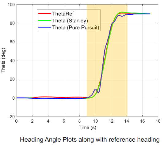
Determine 8: Heading Angle Plots Comparisons (©Buckeye AutoDrive)
Alerts and Indicators Interactions

Determine 9: Navigation Logic (©Buckeye AutoDrive)
Collision Avoidance
Adaptive Cruise Management (ACC) was switched on when objects had been detected inside 25m of the ego automobile. ACC parameters reminiscent of default spacing, prediction horizon, acceleration vary, pattern time, and most velocity had been set. Time hole was modified primarily based on the detected scene. Determine 10 reveals the ACC system.
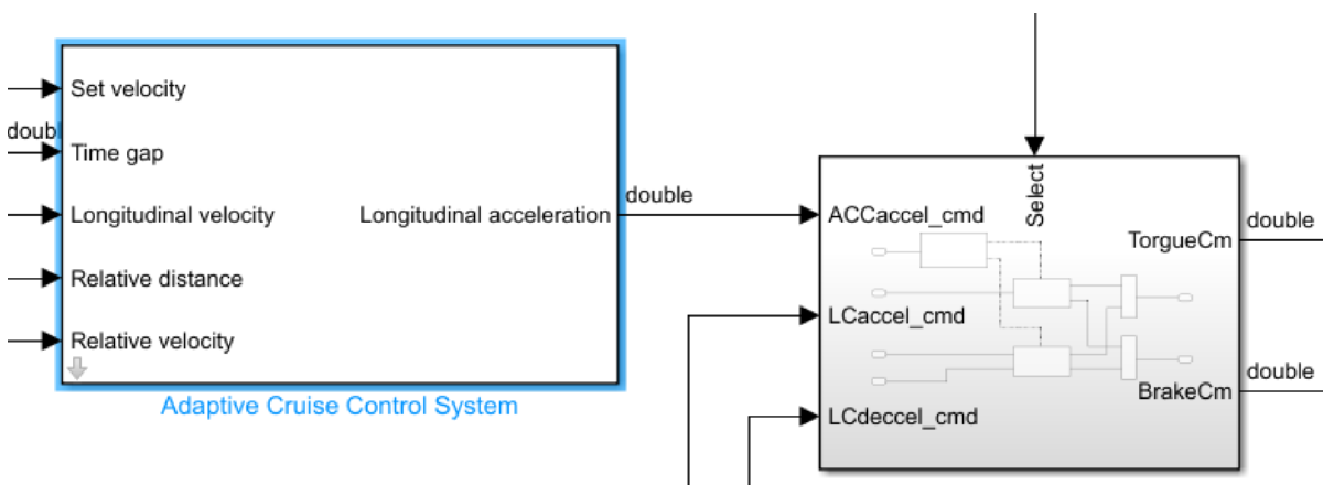
Determine 10: ACC System (©Buckeye AutoDrive)
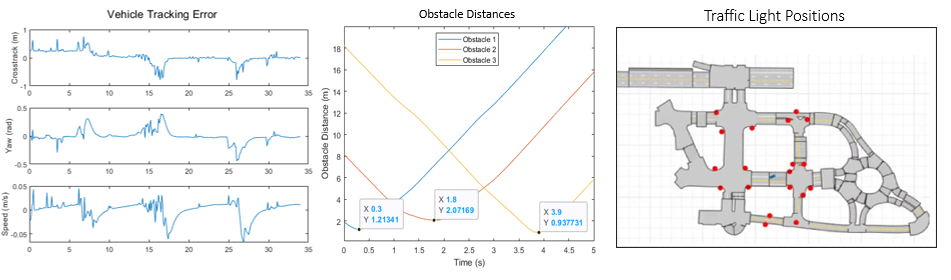
Determine 11 reveals lead and ego automobile velocities, and relative and secure distance outcomes when time hole was set to 1. The ego automobile by no means exceeded set velocity.
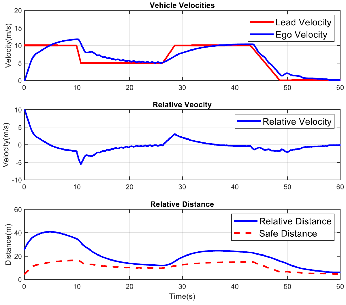
Determine 11: Collision Avoidance Outcomes (©Buckeye AutoDrive)
Automated Code Era and SIL Testing
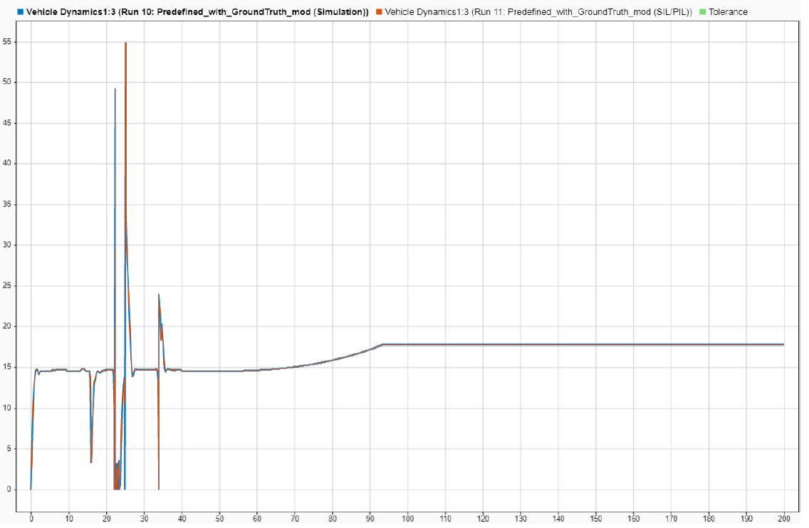
Determine 12: MIL and SIL Comparability Outcomes (©Buckeye AutoDrive)
Challenges and Options
The group confronted a number of challenges alongside the way in which, primarily in code technology. They observed a sampling time mismatch between completely different subsystems, Utilization of transition blocks to be able to get a uniformed pattern fee fastened this drawback. The group additionally changed their swap block with a saturation block to resolve mismatch of velocity and path inputs to their controller block. Decrease velocity values had been inflicting the simulations to decelerate. The group put a decrease velocity restrict of 0.001m/s to resolve this drawback.
Conclusion
In abstract, the profitable groups of the AutoDrive II Y1 MathWorks Simulation Problem used MATLAB and Simulink to design, check, and validate their planning and controls methods. College of Toronto’s group carried out automated testing of their system-level necessities, and used Pugh matrices to guage a number of planners and controllers. The Ohio State College’s group switched between operation modes for navigation utilizing Stateflow, and in contrast system efficiency in SIL and MIL.