In as we speak’s put up, Akshra Ramakrishnan will speak about easy methods to write practical necessities for a driving situation made in Driving Situation Designer, and write take a look at instances to confirm and validate these necessities. Over to you, Akshra..
Situation and Mannequin Overview:
The situation that I will probably be utilizing and writing necessities for accommodates one ego automobile, a proper flip, one site visitors gentle and one cease signal. The ego automobile’s path is pre-defined.
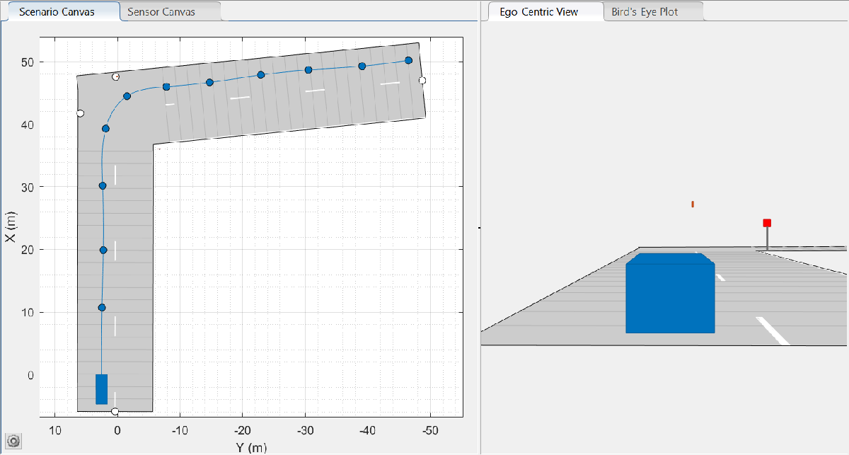
Determine 1: DSD situation with 1 site visitors gentle and 1 cease signal
The Simulink mannequin I will probably be utilizing accommodates the next subsystems
- Automobile Dynamics: accommodates the automobile dynamics mannequin for a selected automobile. This subsystem outputs the ego automobile states (place, velocity, acceleration, orientation, and angular velocity).
- Situation floor fact: accommodates the situation floor fact info for the chosen situation. This consists of the situation reader block which takes a Driving Situation Designer file as enter and outputs the actor poses and lane boundaries. This subsystem additionally accommodates a few transformation blocks that carry out the required coordinate and unit transformation.
- Necessities: This subsystem accommodates a customized block that reads all of the site visitors lights and cease indicators actor ID from the workspace. Necessities written will probably be linked to this block.
- Site visitors lights and indicators: This subsystem accommodates the site visitors gentle sensor block which hosts a Stateflow chart that assigns site visitors gentle states (colours) to all of the site visitors lights within the situation. Site visitors gentle states are then handed to a operate block that maps them to the proper site visitors gentle ID. This outputs a bus that accommodates site visitors gentle states, ID, and positions for every site visitors gentle within the situation. One other operate block does the identical for cease indicators, minus the states.
- Visualization: The visualization block supplies a 2D visualization of the situation, ego automobile path, site visitors gentle positions and states, and cease signal positions.
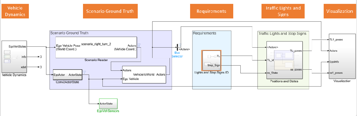
Determine 2: Simulink mannequin overview
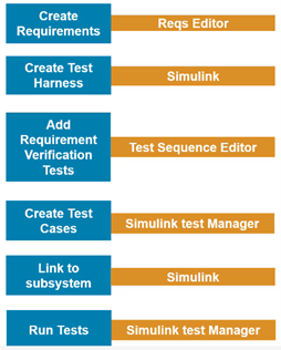
Including Necessities Utilizing Necessities Editor
This part exhibits easy methods to outline system necessities, and add necessities to a block.
Step 1: Outline the system necessities
When following a model-based-design workflow, step one is all the time specifying the system necessities. This ensures that every one members of your crew are on the identical web page concerning system design objectives for the 12 months. For an autonomous system, this may vary from sensor specs (subject of view (FOV), vary and many others.), ego automobile most velocity limitations, system efficiency targets to situation variation necessities.
On this instance, I’m defining two easy situation necessities:
- The variety of site visitors lights within the situation is 1
- The variety of cease indicators within the situation is 1
Step 2: Add necessities to a block
Choose the required Simulink block (Lights and Cease Indicators ID). Open ‘necessities editor’ within the ‘Apps’ tab –> Choose ‘New Necessities Set –> Give a file identify. This creates a .slreqx file which exhibits up within the necessities editor. You possibly can add a number of necessities underneath a necessities set. I’m including the beforehand talked about two necessities to this set, with their requirement IDs 1 and a couple of.
Check Case Verification utilizing Simulink Check Supervisor
As soon as necessities are added, take a look at instances should be written to confirm these necessities.
Step 3: Add take a look at instances to a take a look at suite
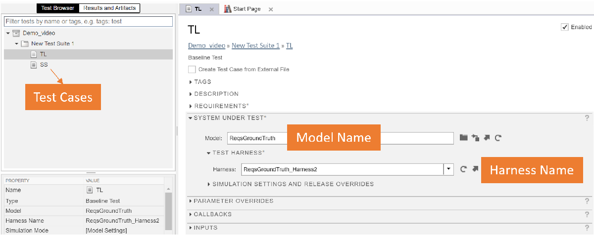
Determine 4: Simulink Check Supervisor
Step 3.1: Create a take a look at harness
A take a look at harness is a test-specific simulation surroundings. You possibly can insolate blocks for unit testing, add verification logic, and take a look at components of your mannequin earlier than you make adjustments to the ultimate mannequin. I will probably be including 2 take a look at evaluation blocks to confirm my two necessities.
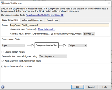
Determine 5: Making a take a look at harness
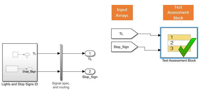
Determine 6: Exterior take a look at harness with take a look at evaluation block
Step 3.2: Including verification logic
In a take a look at case, you’ll be able to:
- Evaluate simulation output to baseline knowledge
- Evaluate the output if two simulations
- Put up-process simulation output utilizing a customized script
- Run-time assessments
In a take a look at harness or mannequin, you’ll be able to:
- Confirm logical circumstances in run-time utilizing a confirm assertion, which returns a go, fail, or untested consequence for every time step.
- Use assert statements to cease simulation on a failure.
- Use blocks from the Mannequin Verification or Simulink® Design Verifier™ library.
- Variety of site visitors lights is 1
- Variety of cease indicators is 1
I solely have one step – the verification step. I’m checking the variety of parts within the arrays ‘TL’ and ‘Stop_Sign’ (these arrays comprise the IDs of all of the site visitors lights and cease indicators in a situation and is given as enter to the ‘Lights and Cease Indicators ID’ block). Add the next traces within the ‘Check Sequence’ Editor.
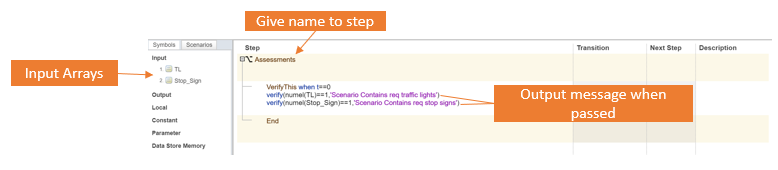
Determine 7: Check sequence editor
Step 4: Hyperlink necessities to check case
I want so as to add my first requirement to the created ‘TL’ take a look at case within the present take a look at suite.
Choose ‘Necessities’ in Check Supervisor –> Add –> New Requirement –> Doc kind as Requirement Set -> Choose beforehand saved requirement set .slreqx file –> Present requirement ID.
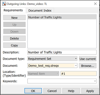
Determine 9: Add requirement to check case
So as to hyperlink the requirement to the take a look at case, proper click on on the block –> Necessities –> Hyperlink to present take a look at case. Be certain the required take a look at case is chosen within the take a look at supervisor earlier than linking.
Create the ‘SS’ take a look at case to the take a look at suite and add requirement #2 to it. The take a look at harness created in Step 3.1 has verification logic for each the necessities, therefore could be specified for each the ‘TL’ and ‘SS’ take a look at instances. Observe the steps for including and linking requirement to a take a look at case.
Step 5: Hyperlink necessities to subsystem
Within the necessities editor, choose requirement –> Proper click on –>Hyperlink from subsystem. This makes positive that subsystems and take a look at instances are appropriately linked to the necessities and could be navigated kind the necessities editor.
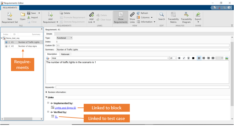
Determine 10: Linking necessities to dam and take a look at case
The necessities editor now accommodates the take a look at suite with two necessities. These are linked to a block and verified by a take a look at case.
Step 6: Verification and implementation
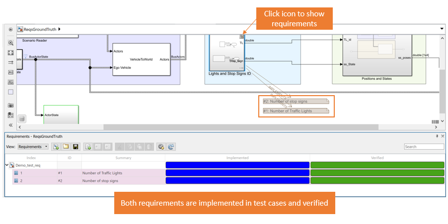
Proper click on on the necessities within the Simulink requirement view –> Examine implementation and verification. This provides two tabs that present the standing of that requirement.
So as to run all of the take a look at instances and generate a take a look at report, go to Check supervisor –> Check browser –> Examine generate take a look at report. Right here you’ll be able to choose and fill in info that you really want in your take a look at report. Run all of the take a look at instances.
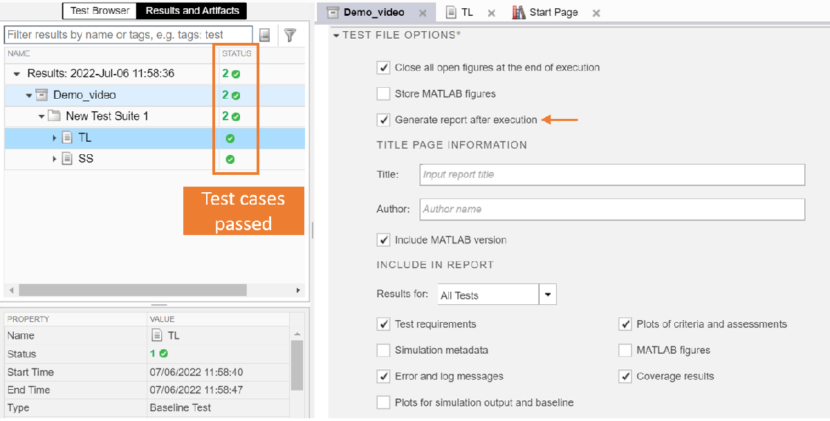
The inexperienced test marks present which necessities handed which take a look at case. The generated take a look at report has all this info, together with plots on the standing of necessities in every timestep.
Abstract
In conclusion, we noticed easy methods to write necessities for a DSD situation utilizing necessities editor, create take a look at instances utilizing Simulink take a look at, create take a look at harness for necessities verification, and confirm and validate necessities for all of the take a look at instances inside a take a look at suite.