

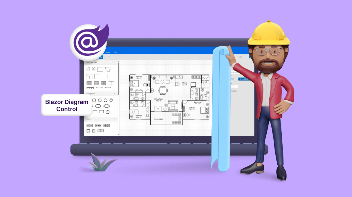
TLDR: Create intuitive ground planners for inside design, actual property, and extra with the versatile options of the Syncfusion Blazor Diagram Library. Uncover its drag-and-drop performance, copy-and-paste instruments, and seamless import/export options, which streamline the ground planning course of.
A ground planner is a software for creating ground plans and room layouts for varied functions, together with inside design, structure, actual property, and facility administration. With this, customers can organize and visualize rooms, partitions, furnishings, home equipment, and different objects inside a given area.
The Blazor Diagram part is a quick and highly effective library for visualizing, creating, and enhancing interactive diagrams. It helps creating flowcharts, organizational charts, thoughts maps, and extra.
Let’s see tips on how to use the Blazor Diagram Library to create an interactive consumer interface that empowers designers to swiftly and effortlessly create ground planners.
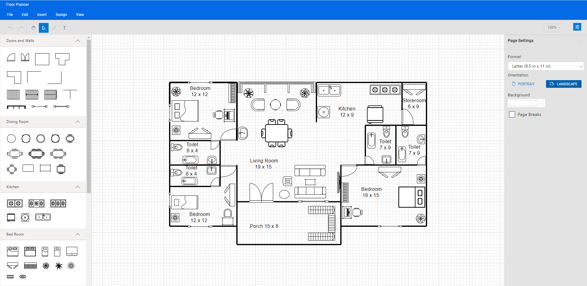
Seek advice from the next picture.
Configuring the Blazor Diagram Library
Observe these steps to configure the Syncfusion Blazor Diagram part:
- First, create a Blazor WebAssembly or server app.
- Then, set up the Syncfusion.Blazor.Diagram the NuGet bundle within the app utilizing the NuGet bundle supervisor.
- Add the scripts and magnificence assets by way of CDN or from the NuGet bundle within the head factor of your index.html web page within the ~/wwwroot/ listing.
<head> ……… ……… <hyperlink href="https://www.syncfusion.com/blogs/put up/_content/Syncfusion.Blazor.Themes/bootstrap5.css" rel="stylesheet" /> <script src="https://cdn.syncfusion.com/blazor/20.4.38/syncfusion-blazor.min.js" sort="textual content/javascript"></script> </head> - Open the ~/_Imports.Blazorfile and import the Syncfusion.Blazor.Diagram bundle in it.
@utilizing Syncfusion.Blazor.Diagram
- Within the Program.cs file, add the companies required for the Syncfusion elements utilizing the builder.Companies.AddSyncfusionBlazor() extension technique.
utilizing Syncfusion.Blazor;
var builder = WebAssemblyHostBuilder.CreateDefault(args);
. . . . .
. . . . .
builder.Companies.AddSyncfusionBlazor();
await builder.Construct().RunAsync();
- Lastly, add the Blazor Diagram part to the Pages folder within the Razor file.
<SfDiagramComponent @ref="@Diagram" @bind-Width="@DiagramWidth" @bind-Top="@DiagramHeight" >
  </SfDiagramComponent>
After executing the above code examples, the Blazor Diagram Library can be built-in into your app. The next picture reveals the essential canvas of the Blazor Diagram part.

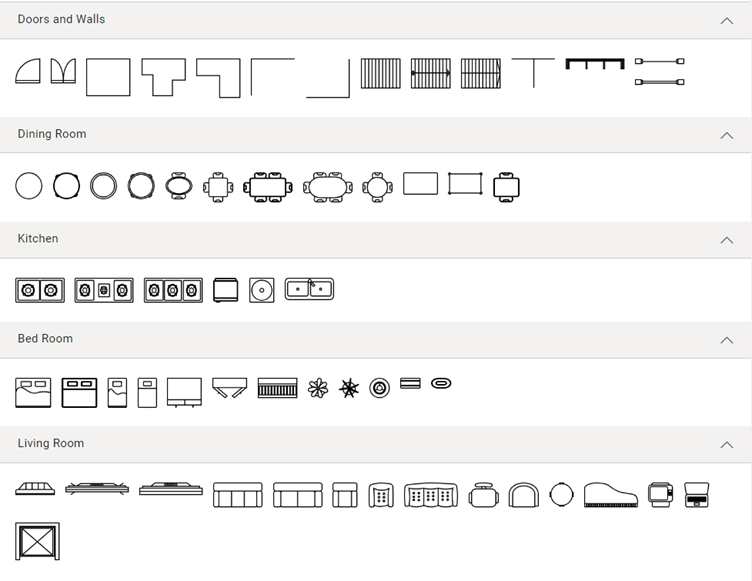
Ground planner diagram symbols
The ground planner designer presents a wide range of symbols, similar to doorways, partitions, eating, kitchen, dwelling rooms, and different elements, to assist design complete ground planner diagrams.
Creating reusable ground planner symbols
The Blazor Diagram management presents a gallery of reusable nodes and connectors known as SymbolPalette. These palettes show a group of shapes, and every palette showcases a set of nodes and connectors. You possibly can simply drag and drop these symbols onto the diagram canvas as wanted.
Now, let’s see the steps to create a diagram image palette with the ground planner shapes:
- First, create an HTML div factor to behave because the container for the diagram’s image palette.
<div class="db-palette-parent">
</div>
- Initialize the Syncfusion Diagram’s image palette with the gathering of symbols to be included within the palette. Additionally, configure the properties similar to Top, Width, SymbolHeight, SymbolWidth and extra to outline uniform dimensions for all shapes within the palette.
<SfSymbolPaletteComponent @ref="@PaletteInstance" Width="100%" Top="100%" SymbolHeight="@symbolSizeHeight" SymbolWidth="@symbolSizeWidth" GetSymbolInfo="GetSymbolInfo" Palettes="@Palettes" SymbolDragPreviewSize="@SymbolPreview" SymbolMargin="@SymbolMargin"> </SfSymbolPaletteComponent>
- Then, outline your palette symbols and customise them as wanted.
SfSymbolPaletteComponent? PaletteInstance { get; set; }

/// <abstract>
/// Will get or units the image preview measurement for an merchandise within the Image Palette.
/// </abstract>
DiagramSize SymbolPreview = new DiagramSize();
/// <abstract>
/// Will get or units the image preview margin for an merchandise within the Image Palette.
/// </abstract>
SymbolMargin SymbolMargin = new SymbolMargin { Left = 2, Proper = 2, High = 2, Backside = 2 };
/// <abstract>
/// Will get or units the image width for an merchandise within the Image Palette.
/// </abstract>
double symbolSizeWidth;
/// <abstract>
/// Will get or units the image peak for an merchandise within the Image Palette.
/// </abstract>
double symbolSizeHeight;
/// <abstract>
/// Reference to the palettes within the image palette.
/// </abstract>
DiagramObjectCollection<Palette>? Palettes { get; set; }

/// <abstract>
/// Will get or units the Door form symbols.
/// </abstract>
public DiagramObjectCollection<NodeBase> DoorSymbols { get; set; } = new DiagramObjectCollection<NodeBase>();
/// <abstract>
/// Will get or units the DiningRoom form symbols.
/// </abstract>
public DiagramObjectCollection<NodeBase> DiningRoomSymbols { get; set; } = new DiagramObjectCollection<NodeBase>();
/// <abstract>
/// Will get or units the Kitchen form symbols.
/// </abstract>
public DiagramObjectCollection<NodeBase> KitchenSymbols { get; set; } = new DiagramObjectCollection<NodeBase>();
/// <abstract>
/// Will get or units the BedRoom form symbols.
/// </abstract>
public DiagramObjectCollection<NodeBase> BedRoomSymbols { get; set; } = new DiagramObjectCollection<NodeBase>();
/// <abstract>
/// Will get or units the LivingRoom form symbols.
/// </abstract>
public DiagramObjectCollection<NodeBase> LivingRoomSymbols { get; set; } = new DiagramObjectCollection<NodeBase>();
/// <abstract>
/// Will get or units the BathRoom form symbols.
/// </abstract>
public DiagramObjectCollection<NodeBase> BathRoomSymbols { get; set; } = new DiagramObjectCollection<NodeBase>();


protected override void OnInitialized()
{
    symbolSizeWidth = 50;
    symbolSizeHeight = 50;
    SymbolPreview = new DiagramSize();
    SymbolPreview.Width = 50;
    SymbolPreview.Top = 50;
    //Initializes the palette.
    InitializePalettes();
    Palette Door = new Palette() { Symbols = DoorSymbols, Title = "Doorways and Partitions", ID = "Door", IconCss = "e-ddb-icons e-flow" };
    Palette DiningRoom = new Palette() { Symbols = DiningRoomSymbols, Title = "Eating Room", ID = "DiningRoom", IconCss = "e-ddb-icons e-flow" };
    Palette Kitchen = new Palette() { Symbols = KitchenSymbols, Title = "Kitchen", ID = "Kitchen", IconCss = "e-ddb-icons e-flow" };
    Palette BedRoom = new Palette() { Symbols = BedRoomSymbols, Title = "Mattress Room", ID = "BedRoom", IconCss = "e-ddb-icons e-flow" };
    Palette LivingRoom = new Palette() { Symbols = LivingRoomSymbols, Title = "Residing Room", ID = "LivingRoom", IconCss = "e-ddb-icons e-flow" };
    Palette BathRoom = new Palette() { Symbols = BathRoomSymbols, Title = "Bathtub Room", ID = "BathRoom", IconCss = "e-ddb-icons e-flow" };
    Palettes = new DiagramObjectCollection<Palette>();
    if (Palettes != null)
    {
        Palettes.Add(Door);
        Palettes.Add(DiningRoom);
        Palettes.Add(Kitchen);
        Palettes.Add(BedRoom);
        Palettes.Add(LivingRoom);
        Palettes.Add(BathRoom);
    }
}
/// <abstract>
/// This technique used to render the nodes or connectors within the Image Palette.
/// </abstract>
        non-public void InitializePalettes()
        {
            DoorSymbols = new DiagramObjectCollection<NodeBase>()
            {
                new Node()
                {
                    ID = "Doorclose",
                    Width = 25,
                    Top = 25,
                    Tooltip= new DiagramTooltip()
                    {
                        Content material="Door shut"
                    },
                    Constraints = (NodeConstraints.Default | NodeConstraints.Tooltip),
                    Form = new PathShape()
                    {
                        Information = "M1 71L1 79L72 79V71M1 71L72 71M1 71C1 32.3401 32.3401 1 71 1H72V71"
                    }
                },
                new Node()
                {
                    ID = "Doubledoorclose",
                    Width = 25,
                    Top = 25,
                    Tooltip= new DiagramTooltip()
                    {
                        Content material="Double door shut"
                    },
                    Constraints = (NodeConstraints.Default | NodeConstraints.Tooltip),
                    Form = new PathShape()
                    {
                        Information = "M143 71V79L1 79L1 71M143 71L1 71M143 71V1H142C103.34 1 72 32.3401 72 71M143 71H72M1 71L1 1H2C40.6599 1 72 32.3401 72 71M1 71L72 71M72 78.5V71"
                    }
                },
                new Node()
                {
                    ID = "Room",
                    Width = 45,
                    Top = 38,
                    Tooltip= new DiagramTooltip()
                    {
                        Content material="Room"
                    },
                    Constraints = (NodeConstraints.Default | NodeConstraints.Tooltip),
                    Form = new PathShape()
                    {
                        Information = "M4 4H104V104H4V4Z"
                    }
                }, …
            };
You may get the code for all of the reusable symbols used on this pattern right here.
The next screenshot reveals the gathering of ground planner shapes within the image palette.
Observe: Seek advice from the Image palette in Blazor Diagram documentation for extra particulars on including, grouping, and customizing the image palette.
Making a ground planner design utilizing the Blazor Diagram Library
Now, we are able to simply design the ground planner diagram by including it to the diagram canvas.
Step #1: Including ground planner symbols to the editor
You possibly can create the design by dragging the specified ground planner symbols from the image palette and dropping them onto the diagram floor on the desired location.
Seek advice from the next picture.
Step #2: Altering the symbols’ place
You possibly can change the place of the dropped image by merely clicking and dragging it to the specified location within the diagram canvas.
Seek advice from the next picture.
Step #3: Loading and saving the diagram
The Blazor Diagram Library supplies a helpful function that allows you to save your work and resume it later by loading the saved diagram.
To save lots of your present diagram, choose Save from the File menu. This motion will save your diagram as a file in your native drive.
To load an present diagram file, navigate to the File -> Open menu. This may open the file dialog field, permitting you to browse and choose the saved diagram file you want.
This function supplies nice flexibility and comfort, permitting you to simply choose up the place you left off on a diagram or make modifications to a beforehand saved diagram. It’s a necessary function for any diagramming app that permits customers to create and handle complicated diagrams.
Seek advice from the next GIF picture.
Observe: For extra particulars, seek advice from loading and saving diagrams within the Blazor Diagram Library documentation.
Step #4: Undo or redo the diagram motion
The Blazor Diagram part helps undo and redo operations, permitting you to trace modifications made to a diagram. These options are important for shortly correcting errors or restoring the beforehand undone motion.
To undo an motion, use the Ctrl + Z keyboard shortcut, or click on the Undo button on the toolbar, or use the Undo instructions from the Edit menu. This may revert the latest motion carried out.
To redo an motion, use the Ctrl + Y keyboard shortcut, or click on the Redo button on the toolbar, or use the Redo instructions from the Edit menu. This may redo probably the most not too long ago undone motion.
Step #5: Exporting the diagram
It’s also possible to export the created ground planner diagram as a picture file in several codecs similar to JPEG, PNG, and SVG. By exporting the diagram as a picture, you’ll be able to simply share it through e-mail or different digital means or embed it in a doc or presentation.
To export a diagram, click on the File menu and choose Export. A dialog field will seem, permitting you to specify the title and picture file format to avoid wasting the ground planner diagram. Moreover, you’ll be able to export solely the content material space of the diagram by excluding the clean areas or export the complete diagram (together with clean areas) primarily based on the width and peak specified within the web page settings.
Step #6: Printing the diagram
To print a diagram, click on the File menu and choose Print. The Print dialog field will open, and you’ll select your printer and customise the print settings, similar to orientation, paper measurement, and web page margins. Then, click on the Print button to print the ground planner diagram.
Step #7: Pan and zoom
The Blazor Diagram Library presents varied panning and zooming choices to navigate by way of your diagrams effectively.
- Pan utilizing the scrollbars: Essentially the most easy option to pan a diagram is by utilizing the scrollbars on the appropriate aspect and backside of the diagram canvas. This lets you scroll the diagram in any route you want.
- Pan utilizing the mouse wheel: You possibly can pan a diagram by rotating the mouse wheel. To scroll up or down, rotate the mouse wheel ahead or backward; to scroll left or proper, maintain Shift whereas rotating the scroll wheel ahead or backward.
- Pan utilizing the pan software: You possibly can pan a diagram by deciding on the Pan software from the toolbar. Click on and maintain down the left mouse button, then drag the mouse to maneuver the diagram in any route.
- Zoom utilizing keyboard shortcuts: Essentially the most environment friendly option to zoom out and in of the diagram is to make use of the Ctrl + mouse wheel shortcut.
- Zoom utilizing the toolbar choice: It’s also possible to zoom in or out in a diagram utilizing the zoom dropdown within the upper-right nook of the app window. Within the Zoom dropdown, you’ll be able to choose the Zoom To Match choice to suit the complete ground planner diagram to the window.
GitHub reference
Additionally, you’ll be able to obtain the Blazor ground planner diagram demo on GitHub.
Conclusion
Thanks for studying! On this weblog, we’ve realized tips on how to effortlessly create a ground planner diagram utilizing the Syncfusion Blazor Diagram Library. It’s also possible to use the Diagram part to create organizational charts, flowcharts, thoughts maps, community diagrams, or logic circuit diagrams. Attempt it out and depart your suggestions within the feedback part beneath!
If you happen to’re an present Syncfusion consumer, obtain the newest model of Important Studio from the License and Downloads web page. If you happen to’re new to Syncfusion, you need to use our 30-day free trial to discover the options and capabilities of our elements.
For questions, you’ll be able to attain us by way of our help discussion board, help portal, or suggestions portal. We’re at all times completely happy to help you!