

1. Introduction
UML (Unified Modeling Language) is a visible modeling language utilized in software program engineering to characterize complicated programs. It’s a standardized language for visualizing, specifying, establishing, and documenting the artifacts of software program programs. UML can be utilized to mannequin numerous kinds of programs, together with software program, {hardware}, and enterprise processes. It offers a wealthy set of notations for creating diagrams that may assist to speak complicated concepts and designs to stakeholders. UML was developed by the Object Administration Group (OMG) and has develop into a extensively used customary within the software program business. It’s frequently evolving, with new variations and updates being launched to enhance its capabilities and value.
2. Structural Diagrams
Structural diagrams are helpful for modeling the construction of a system and can be utilized to doc and talk the structure of a software program system. They can be utilized to explain the group of lessons, objects, parts, and nodes in a system, and the relationships between them. By creating structural diagrams, builders can be certain that a system’s parts are correctly organized and that the relationships between them are clearly outlined.
2.1 Class Diagram
A category diagram is a kind of structural diagram in UML that describes the construction of a system by exhibiting its lessons, attributes, operations, and relationships amongst objects.
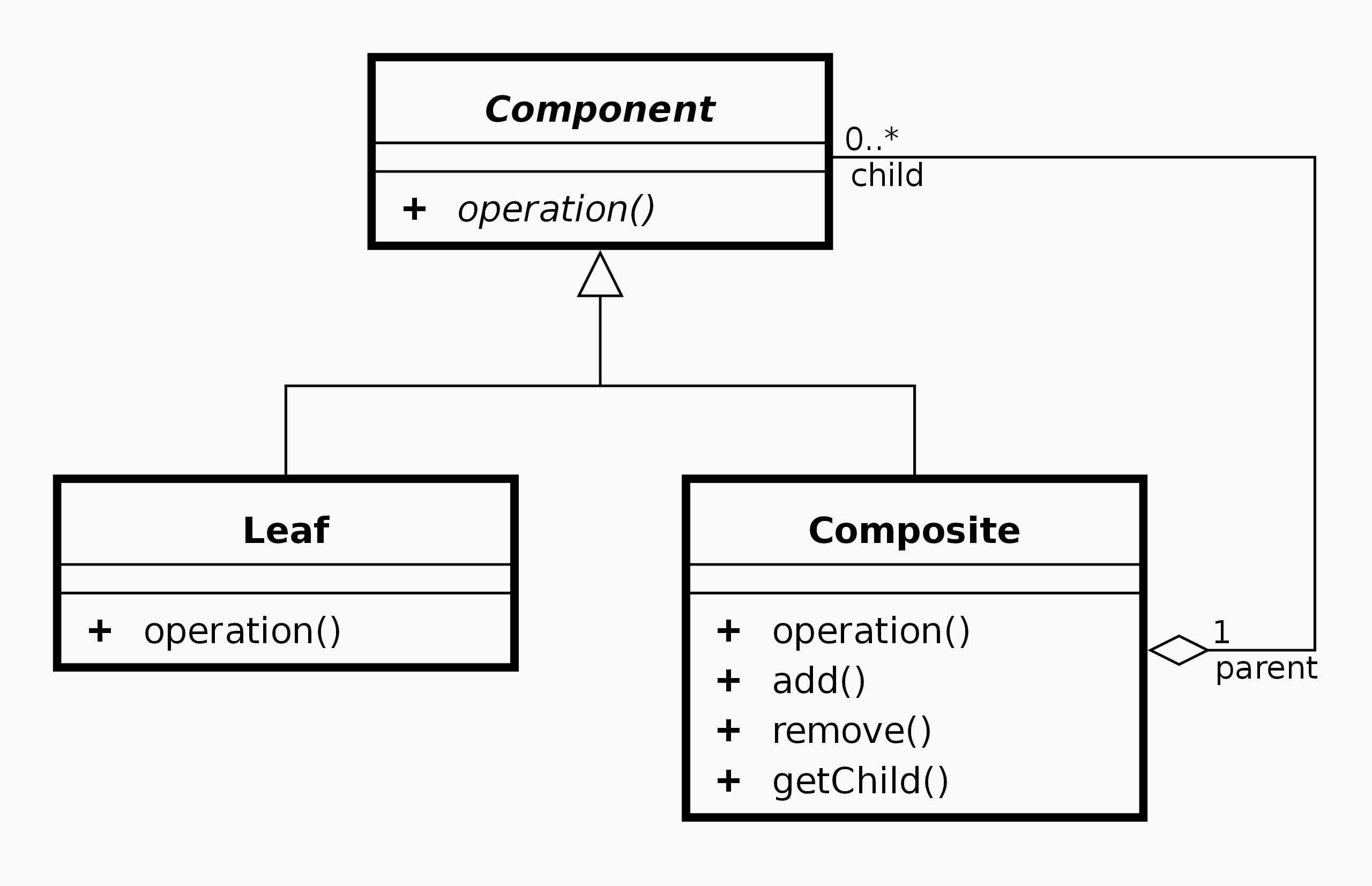
Listed below are some key parts of a category diagram:
| Ingredient | Description |
| Class | A category represents a blueprint or template for creating objects. |
| Attribute | An attribute is a knowledge aspect that describes the state of an object. |
| Operation | An operation is a perform or conduct that an object can carry out. |
| Visibility | The visibility of a category member (attribute or operation) determines whether or not it may be accessed from outdoors the category. |
| Relationship | A relationship represents an affiliation between lessons, resembling inheritance, aggregation, or composition. |
Class diagrams can be utilized to mannequin a variety of programs, from easy to complicated. They might help to make clear the relationships between completely different lessons and present how they work together with one another. Class diagrams will also be used to generate code robotically, in addition to to doc the design of a system.
2.2 Object Diagram
An object diagram is a kind of structural diagram in UML that shows a set of objects and their relationships at a particular cut-off date. It represents a snapshot of a system’s state, exhibiting the objects and their attributes and relationships at a particular second.
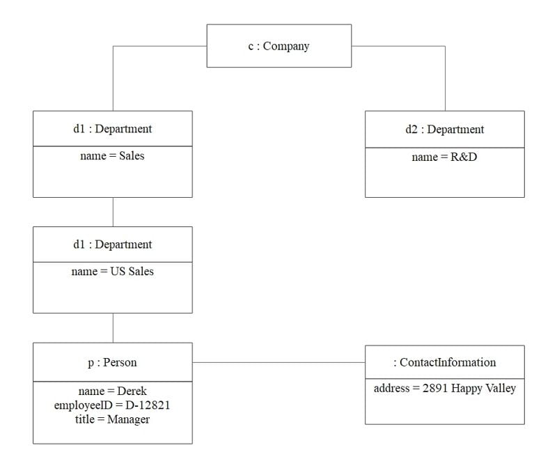
Listed below are some key parts of an object diagram:
| Ingredient | Description |
| Object | An object represents an occasion of a category at a specific cut-off date. |
| Attribute | An attribute is a knowledge aspect that describes the state of an object. |
| Relationship | A relationship represents an affiliation between objects, resembling a composition or an aggregation. |
Object diagrams can be utilized to confirm {that a} system’s design is appropriate by testing it in opposition to particular situations. They will also be used to determine points and inconsistencies within the design of a system. Object diagrams might help builders to grasp how completely different objects work together with one another, and the way adjustments to 1 object can have an effect on different objects within the system.
2.3 Part Diagram
A element diagram is a kind of structural diagram in UML that depicts the group of bodily or logical parts of a system. It reveals the relationships between parts and the way they’re linked to kind a system.
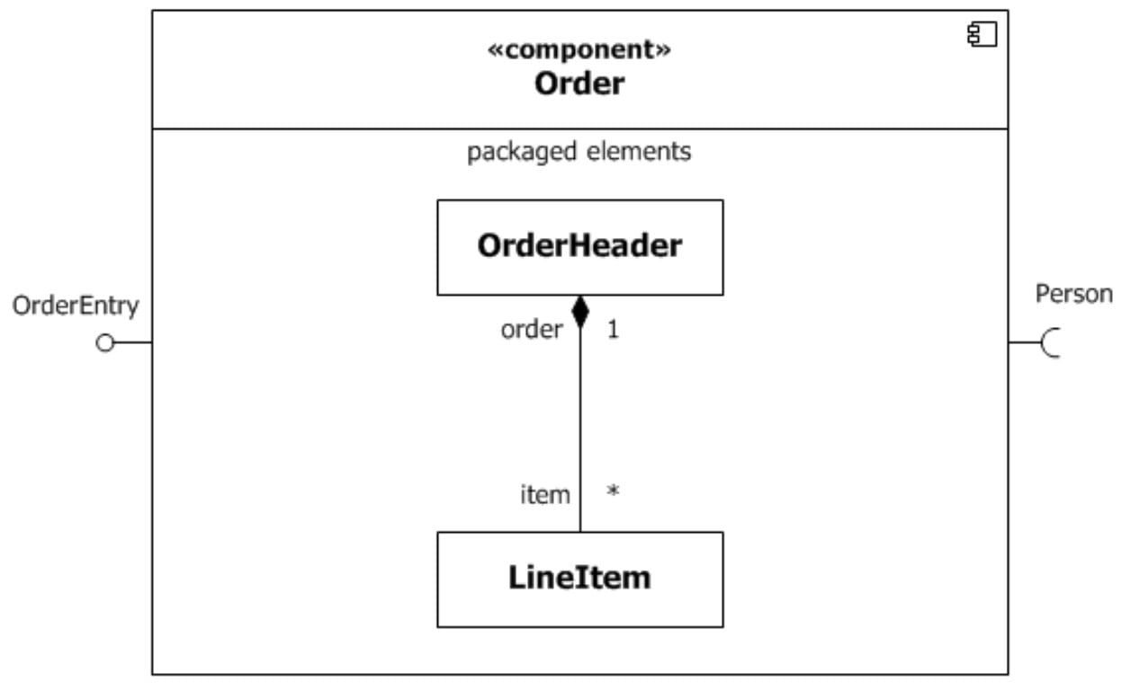
Listed below are some key parts of a element diagram:
| Ingredient | Description |
| Part | A element represents a modular a part of a system that encapsulates its conduct and knowledge. |
| Interface | An interface is a set of operations {that a} element offers to its setting or to different parts. |
| Relationship | A relationship represents an affiliation between parts, resembling a dependency or a realization. |
| Connector | A connector is a communication mechanism that connects parts and specifies how they work together with one another. |
Part diagrams can be utilized to mannequin the structure of a software program system and to determine its element components. They will also be used to specify the interfaces between parts and to point out how they convey with one another.
2.4 Deployment Diagram
A deployment diagram is a kind of structural diagram in UML that represents the configuration of the run-time processing nodes and the software program parts that reside on them. It reveals the bodily {hardware} and software program parts that make up a system and the relationships between them.
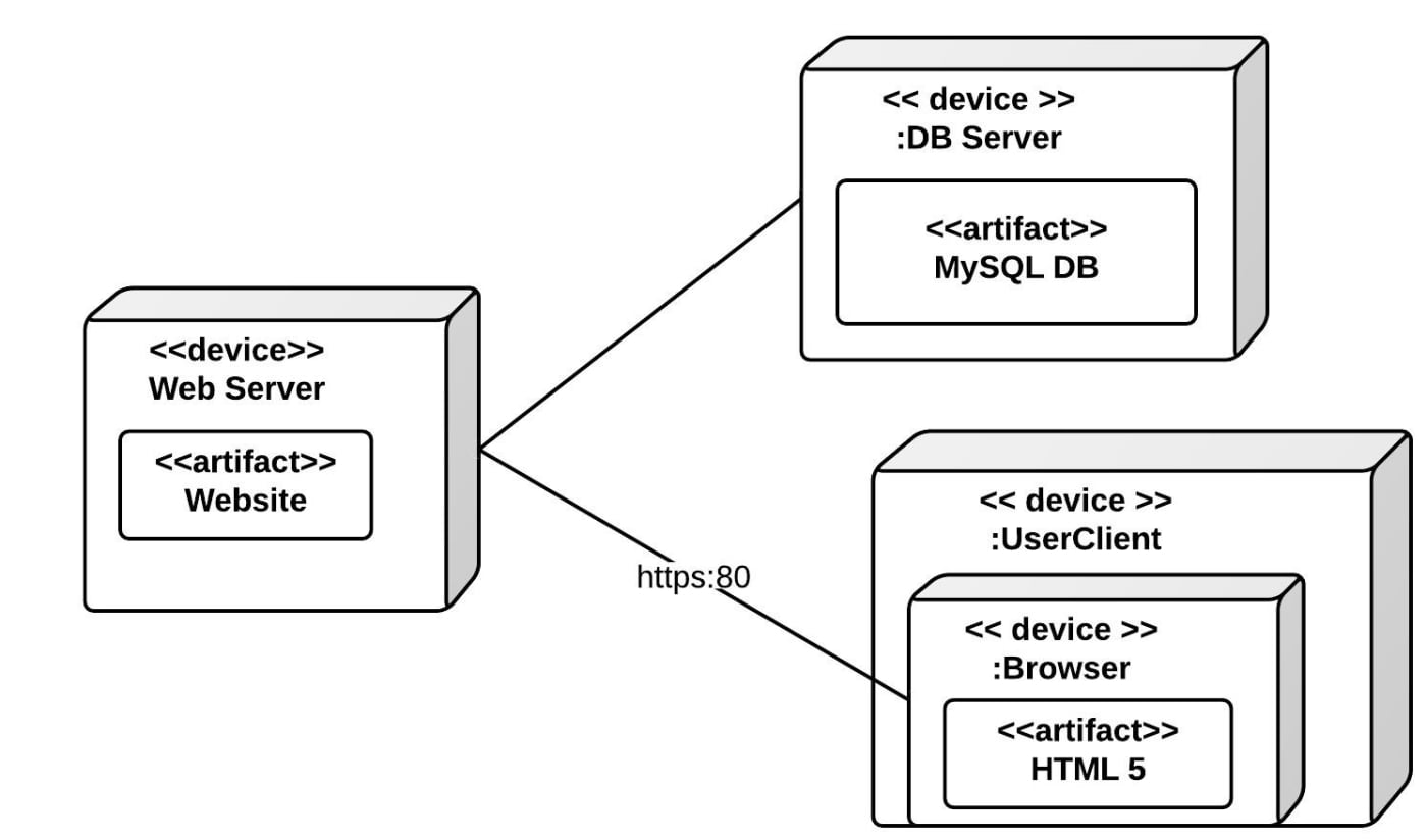
Listed below are some key parts of a deployment diagram:
| Ingredient | Description |
| Node | A node represents a bodily or logical processing aspect, resembling a server, pc, or machine. |
| Part | A element represents a modular a part of a system that encapsulates its conduct and knowledge. |
| Artifact | An artifact represents a bodily file or software program element that’s saved on a node. |
| Relationship | A relationship represents an affiliation between nodes, resembling a communication path or a dependency. |
Deployment diagrams can be utilized to mannequin the bodily infrastructure of a software program system and to determine the {hardware} and software program parts that make up the system. They will also be used to specify the deployment of software program parts throughout completely different nodes and to point out how they convey with one another.
3. Behavioral Diagrams
Behavioral diagrams are a kind of UML diagram that describes the dynamic conduct of a system. They present how objects work together with one another and the way the system responds to completely different occasions and situations. Behavioral diagrams can be utilized to mannequin the conduct of a system over time, resembling throughout a use case situation or a particular course of.
3.1 Use Case Diagram
A use case diagram is a kind of behavioral diagram in UML that describes the interplay between the system and its actors, exhibiting how the system responds to completely different use instances. It reveals the relationships between actors and use instances, and the way the actors work together with the system to attain particular targets.

Listed below are some key parts of a use case diagram:
| Ingredient | Description |
| Actor | An actor is an individual, group, or system that interacts with the system to attain a purpose. |
| Use Case | A use case represents a particular performance or function of the system that gives worth to its actors. |
| Relationship | A relationship represents an affiliation between an actor and a use case, resembling an affiliation or an embody relationship. |
Use case diagrams can be utilized to determine the completely different actors that work together with a system and the completely different use instances that the system helps. They will also be used to determine the completely different situations that actors might encounter when utilizing the system, and to point out how the system responds to those situations.
3.2 Exercise Diagram
An exercise diagram is a kind of behavioral diagram in UML that depicts the move of actions or processes in a system, resembling enterprise processes or software program algorithms. It reveals the sequence of actions and the situations beneath which they happen, in addition to the choice factors and outcomes of every exercise.
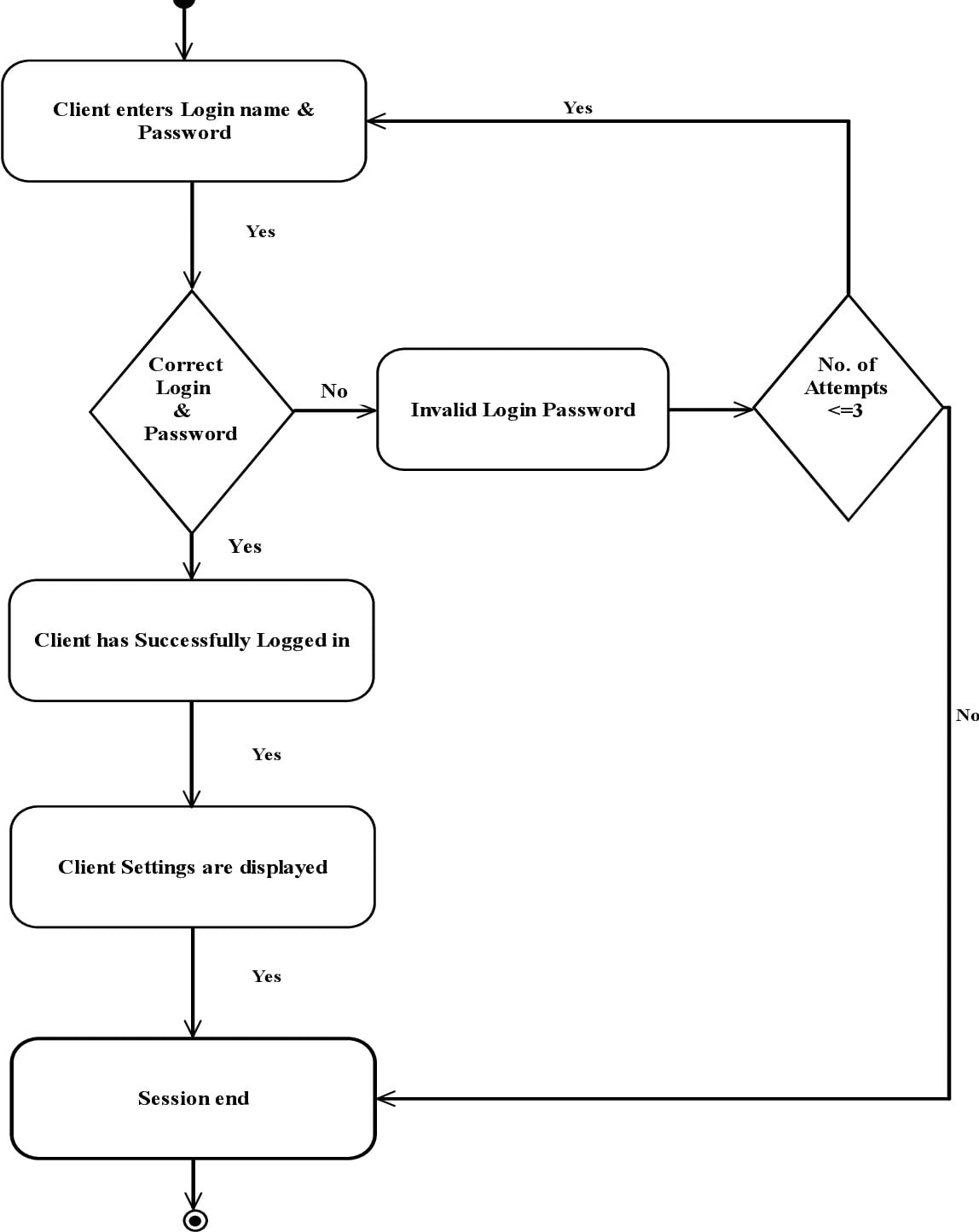
Listed below are some key parts of an exercise diagram:
| Ingredient | Description |
| Exercise | An exercise represents a particular motion or process that’s carried out within the system. |
| Management move | Management move represents the order by which actions are carried out and the situations beneath which they happen. |
| Determination node | A call node represents a degree within the exercise the place a call have to be made based mostly on a particular situation. |
| Merge node | A merge node represents a degree within the exercise the place the management move is mixed from a number of paths. |
Exercise diagrams can be utilized to mannequin complicated workflows, resembling enterprise processes or software program algorithms. They might help builders to grasp the move of actions in a system and to determine potential points and areas for enchancment.
3.3 State Machine Diagram
A state machine diagram is a kind of behavioral diagram in UML that reveals the completely different states of an object and the way it transitions between them in response to occasions. It fashions the conduct of an object over time and reveals the way it responds to completely different stimuli or situations.
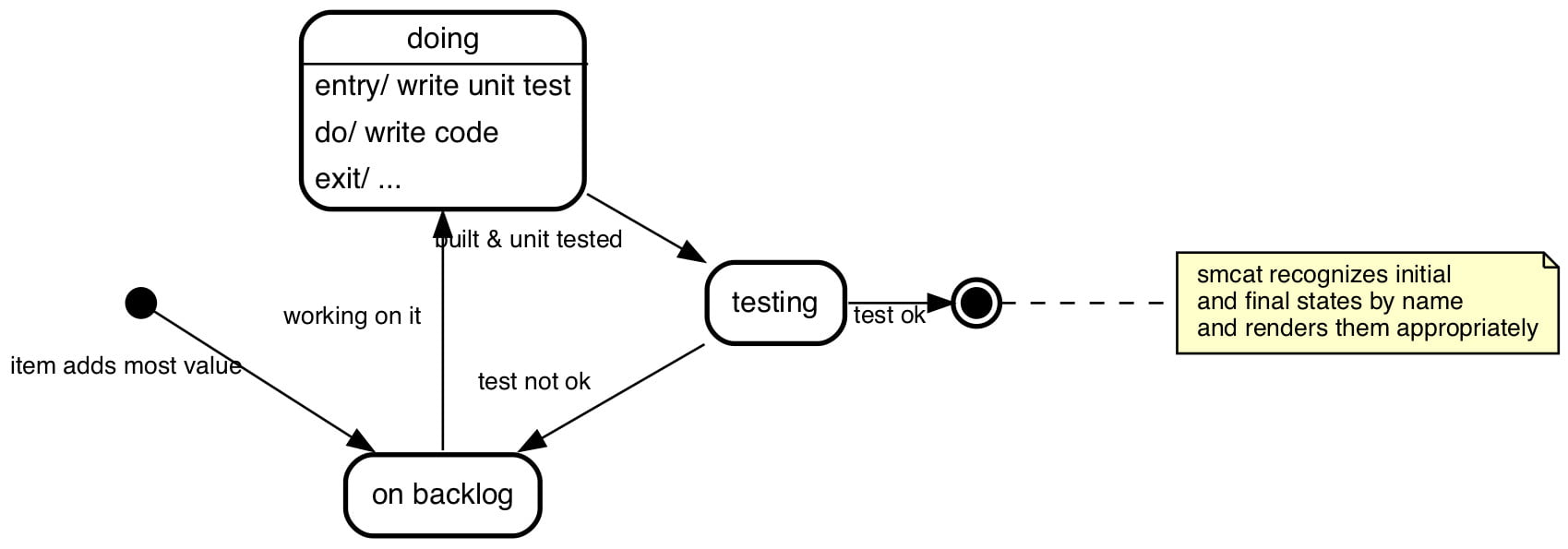
Listed below are some key parts of a state machine diagram:
| Ingredient | Description |
| State | A state represents a situation or mode of an object, resembling “on” or “off”. |
| Transition | A transition represents the change from one state to a different in response to a particular occasion or situation. |
| Set off | A set off represents the occasion or situation that causes a transition to happen. |
| Guard situation | A guard situation represents a constraint or situation that have to be met for a transition to happen. |
State machine diagrams can be utilized to mannequin the conduct of objects in a system and to determine potential points and areas for enchancment. They might help builders to make sure that the conduct of an object is well-defined and constant.
3.4 Package deal Diagram
A package deal diagram is a kind of structural diagram in UML that reveals the group of parts into packages. It depicts the dependencies between packages and the relationships between the weather inside them.
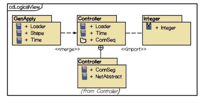
Listed below are some key parts of a package deal diagram
| Ingredient | Description |
| Package deal | A package deal is a container for a bunch of associated parts, resembling lessons, interfaces, or different packages. |
| Dependency | A dependency represents a relationship between two packages, the place one package deal depends upon the opposite for its performance. |
| Affiliation | An affiliation represents a relationship between two parts inside a package deal, resembling a category and an interface. |
| Package deal merge | A package deal merge represents the merging of two or extra packages right into a single package deal. |
Package deal diagrams can be utilized to prepare the weather of a system into logical teams and to determine the dependencies between these teams. They might help builders to handle the complexity of a system by breaking it down into smaller, extra manageable components.
4. Interplay Diagrams
Interplay diagrams are a kind of behavioral diagrams in UML that describe the interactions between objects or parts in a system. There are two predominant kinds of interplay diagrams: sequence diagrams and communication diagrams.
4.1 Sequence Diagram
A sequence diagram is an interplay diagram in UML that reveals the interactions between objects or parts in a time-ordered sequence. It depicts the sequence of messages exchanged between the objects and the order by which they happen.

Listed below are some key parts of a sequence diagram:
| Ingredient | Description |
| Object | An object represents an occasion of a category or element that participates within the interplay. |
| Lifeline | A lifeline represents the time interval throughout which an object exists and participates within the interplay. |
| Message | A message represents a communication between two objects, resembling a technique name or a response. |
| Activation | An activation represents the time frame throughout which an object is executing a technique name. |
Sequence diagrams can be utilized to mannequin the interactions between objects in a system and to determine potential points and areas for enchancment. They might help builders to grasp the sequence of occasions that happen throughout a specific interplay and to make sure that the system behaves as anticipated.
4.2 Communication Diagram
A communication diagram is an interplay diagram in UML that reveals the interactions between objects or parts in a system. It focuses on the relationships between the objects and the messages they change. Communication diagrams are also referred to as collaboration diagrams.
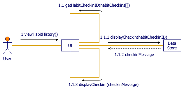
Listed below are some key parts of a communication diagram:
| Ingredient | Description |
| Object | An object represents an occasion of a category or element that participates within the interplay. |
| Hyperlink | A hyperlink represents a connection between two objects and the messages they change. |
| Message | A message represents a communication between two objects, resembling a technique name or a response. |
| Self-message | A self-message represents a message despatched by an object to itself. |
Communication diagrams can be utilized to mannequin the interactions between objects in a system and to determine potential points and areas for enchancment. They might help builders to grasp the relationships between objects and the messages they change, and to make sure that the system behaves as anticipated.
4.3 Timing Diagram
A timing diagram is a kind of interplay diagram in UML that reveals how objects in a system work together with one another over time. It’s used to depict the timing constraints between messages exchanged between objects or parts.
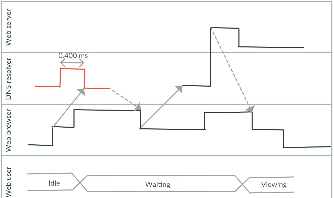
Listed below are some key parts of a timing diagram:
| Ingredient | Description |
| Object | An object represents an occasion of a category or element that participates within the interplay. |
| Lifeline | A lifeline represents the time interval throughout which an object exists and participates within the interplay. |
| Message | A message represents a communication between two objects, resembling a technique name or a response. |
| Period constraint | A length constraint represents a constraint on the period of time a message can take to execute. |
Timing diagrams can be utilized to mannequin the interactions between objects in a system and to determine potential points and areas for enchancment associated to timing. They might help builders to grasp the timing constraints between messages and to make sure that the system meets its timing necessities.
4.4 Interplay Overview Diagram
An interplay overview diagram is a kind of interplay diagram in UML that reveals a high-level view of the interactions between objects or parts in a system. It’s used to mannequin complicated interactions between a number of objects or parts and to simplify their illustration.

Listed below are some key parts of an interplay overview diagram:
| Ingredient | Description |
| Interplay | An interplay represents a sequence of actions or messages that happen between objects or parts within the system. |
| Interplay fragment | An interplay fragment represents part of an interplay that may be reused or repeated. |
| Determination node | A call node represents a degree within the interplay the place a call must be made based mostly on some situation. |
| Merge node | A merge node represents a degree within the interplay the place a number of management flows converge right into a single move. |
Interplay overview diagrams can be utilized to mannequin complicated interactions between objects or parts in a system and to simplify their illustration. They might help builders to grasp the general construction of an interplay and to determine potential points and areas for enchancment.
5. Standard UML Software program
These UML software program instruments are standard amongst builders and groups for modeling software program programs utilizing UML diagrams. They supply numerous options and capabilities to help software program design, growth, and documentation, in addition to crew collaboration and mission administration.
| Software program | Description |
| Visible Paradigm | A complete UML modeling device that helps all UML diagram varieties and offers numerous options for software program growth, mission administration, and crew collaboration. |
| Sparx Methods Enterprise Architect | A robust UML modeling device that helps all UML diagram varieties and offers a spread of options for software program design, growth, and documentation. |
| IBM Rational Software program Architect | A UML modeling device that helps all UML diagram varieties and offers options for software program design, growth, and testing. It additionally helps integration with different IBM software program merchandise. |
| Lucidchart | A cloud-based UML modeling device that helps all UML diagram varieties and offers collaboration options for crew members to work collectively in real-time. |
| StarUML | An open-source UML modeling device that helps all UML diagram varieties and offers primary options for software program design and growth. |
| Gliffy | A cloud-based UML modeling device that helps all UML diagram varieties and offers collaboration options for crew members to work collectively in real-time. It additionally integrates with different software program instruments like JIRA and Confluence. |
| MagicDraw | A UML modeling device that helps all UML diagram varieties and offers a spread of options for software program design, growth, and documentation. It additionally helps integration with different software program instruments and frameworks. |
| PlantUML | An open-source UML modeling device that makes use of a easy text-based syntax to generate UML diagrams. It helps all UML diagram varieties and will be built-in into numerous software program instruments and frameworks. |
| Creately | A cloud-based UML modeling device that helps all UML diagram varieties and offers collaboration options for crew members to work collectively in real-time. It additionally integrates with different software program instruments like Trello and Google Drive. |
| Astah | A UML modeling device that helps all UML diagram varieties and offers options for software program design, growth, and documentation. It additionally helps integration with different software program instruments and frameworks. |
| UMLet | An open-source UML modeling device that gives a easy drag-and-drop interface for creating UML diagrams. |